- P.O. Box 1067
San Marcos, TX 78667 USA - 512.827.3701
Product Categories
Products Details
CGS – Centrifugal Gas Separator
CENTRIFUGALGAS SEPARATOR – CGS TECHNICAL& OPERATING MANUAL
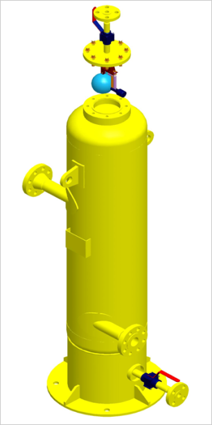
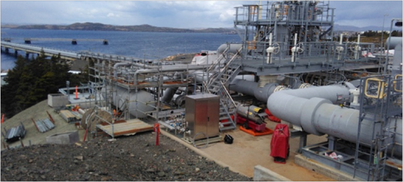
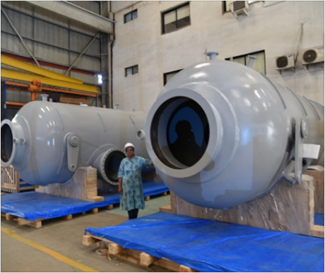
CENTRIFUGALGAS SEPARATOR
Flash Point CGS vertical Centrifugal Gas Separators / Deaerators are designed to Separate and automatically vent out air and gas from petroleum and other Liquid Products before they are metered.
Weight sand Measures Regulators prescribe the installation of Gas Separators for liquids up to 20 m Pas to prevent measuring errors in Volumetric meters, whenever there is a possibility of air or gas entering a metering system during pumped operation.
Standard Specifications:-
Type Model : CGSFabricated Pressure vessel to ASME Sec VIII Div.1
Nominal Pressure Ratings : ANSIB 16.5 Class 150,300 & 600 (Class 900 & 1500 on request)
| OperatingTemp. Range : | (-)29 to 120 Deg C ( Standard Matl no 10 ) (-)46 to 120 Deg C ( LTCS Matl no 11 ) (-)140 to (-)10 Deg C ( SS Matl no16/17) |
| End Connections : | Flangedends to ANSI B 16.5 RF/ RTJ |
| Supports: | SkirtSupports are Standard on all Models |
| StandardSize Range : (VolumeLit.) |
20L,30L,60L,100L,135L,185L,300L,470L,530L,730L,1000L,1400L,1850L, 2200L, 2500L,2750L,3750L,5000L, 6000L,8750L |
| Air Release Vent Type : | Automatic Pilot and Float with counterweight 1 xType AV 125 – For size CGS 20L to CGS 470L 1 xType AV 150 – For Size CGS 530L to CGS 3750L 2 xType AV 150 – For Size CGS 5000L – 8750L |
| MaxOperating Pr of Air Vent Valve : | Type AV 125 – Max W.P. 200 Bar. Type AV 150 – Max W.P. 100Bar. |
| ElastomerSeals : | Optionof BUNA – N , VITON , PTFE, CHEMRAZ |
| Elastomer Seals : | Optionof BUNA – N , VITON , PTFE, CHEMRAZ |
| Optional accessories : | SIGHTGLASS (SG) LEVEL INDICATDR (LG) |
Functional description:-
The fluid enters the Gas Separator through a tangentially constructed inlet nozzle which forces the the liquid into a rotational movement. The rotational downward flow is maintained by the tangentially constructed outlet nozzle at a lower elevation. The centrifugal movement in conjunction with a decrease in flow velocity and pressure, forces mass volumes as well as entrained air and gas (bubbles) to be segregated from the liquid, rise to the upper portion of the vessel and subsequently be automatically released through a pilot & Float Operated air vent valve(AV 125/ AV 150).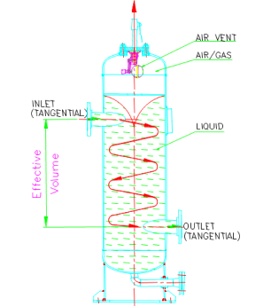
System Design
- The Gas Separator , should under no condition, be operated in excess of the Design conditions (pressure, Temp. & Flow rate) listed on the name plate of the vessel.
- Connect the Gas Separator inlet in accordance with the “ARROW” on the inlet nozzle indicating direction of flow.
- In accordance with Weights and Measures Regulation consideration must be given to the system design to assure a minimum back pressure of 7.5 psig (0.5 Bar)
- In case of Operation with Liquids which have a “foaming” tendency a Sight Glass (SG) must be provided. In such cases the flow should be throttled if foam is noticed at the Sight Glass
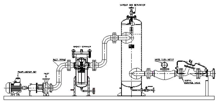
- Gas Separators Should be installed down stream from the pump as close to the meter as possible. ( See typical installation diagram below)
- The air / gas release Should be piped to a vapor recovery system or to a flare at a safe point of discharge . If a manually controlled Valve is provided on the Vent pipe for Safety reasons it should be “LOCKED OPEN” during normal Operation – to be unlocked by authored personnel only.
- Under conditions where flow through the gas Separator needs to be controlled , flow switches (HIGH / LOW / STOP) can be fitted on the Gas Separator to actuate a digital Control Valve (DCV).
- A properly sized strainer should be installed up stream of the Gas Separator to protect the air release Value and prevent clogging during start-up.
Efficiency / Accuracy:-
- CGS Gas Separators are designed to release up to 30% volume of air / gas from the flowing liquid stream at the maximum permissible flow rates mentioned.
-
In order to obtain an effective air/gas separation the following design features have been incorporated in the CGS.
- A fixed ratio between the inside diameter,the fluid velocity between inlet and outlet and the “effective volume” of the vessel. The effective volume of the vessel in litres should be at least 8% of the volume flow rate in LPM.
- A minimum “dwell time“ i.e. time taken for the liquid to transverse from inlet to out let nozzle is kept at 5 seconds.
dwell time is calculated as = (V eff. X 60) / q Max.
where V eff. = effective volume ( Litres)
q Max. = Maximum flowrate ( LPM )
Effective Volume= Liquid Vel. in Vessel (m/sec) x Dwell Time (sec) x Flow Area invessel(m2)
-
Under conditions where :-
- volumes of air / gas are likely to exceed 30% ,
- long pipe walls with several highpoints are present upstream of the meter
- pressure at the pump inlet islikely to fall below at m. pressure or the saturated vapor pressure.
- Air pockets are likely to beintroduced into the pipe work when the supply tank has no “antiswirl” attachment or runs empty.
- Handling liquids with highsaturated vapor pressure.
It may be necessary to either increase the “dwell time” or add a liquid level control system in conjunction with the digital control valve to increase the gas separator efficiency.
MODEL SELECTION CHART
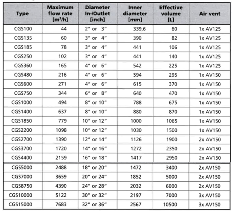
Note:- Inlet / Outlet Sizes other than those listed can be supplied – consult factory
Note:- Larger inlet/outlet sizes if required will have restricted opening areas into vessel
Pressure Drop Chart

DIMENSIONS – CGS

Note:- Dimensionsare Indicative only . For construction dimensions , consult factory for a manufacturing drawing.
DIMENSIONS CGS

WEIGHT ( kgs)

MODEL CODE GENERATION

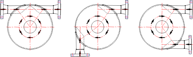
RIGHT HAND SPIN ( Standard)
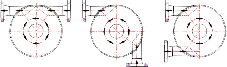
LEFT HAND SPIN
MATERIAL SPECIFICATION

MaterialTest certificate3.1 acc to E N 10204 are standard.
MaterialTest certificate 3.2 where requested can be Supplied.
CERTIFICATIONS STANDARDS &DIRECTIVES
- Gas separator CGS are type tested by NMI, Netherlands and certified to meet with the requirements of OIML R117-1 Ed. 2007E “ Dynamic Measuring Systems for Liquids other than Water “
- Gas separator CGS are designed and manufactured to ASME Sec VIII Div. 1 Pressure vessel construction code.
- Gas separator CGS can be supplied with ASME “U” code stamping
- Gas separator CGS can be supplied under PED (Pressure Equipment Directive) 97 / 23 / E C of E U suitable for Group 1 liquids with classification within category IV with individual acceptance to Module G of PED.
CENTRIFUGALGAS SEPARATOR – CGS TECHNICAL& OPERATING MANUAL